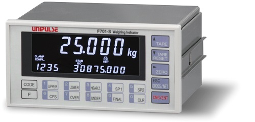
F701-S
Global standard model high performance design weighing indicator


Product outline
F701-S is a weighing indicator with high specifications and various functions such as super-low-drift high-precision amplifier, fast-sampling, weighing sequence functions that are useful for automatic weighing machines and control I/O.
Specifications
Analog section|Setting section|External signal|Display section|General performance|Attachments
| Analog section | |
| Excitation voltage | DC5V±5% Output current:within 90mA Ratio metric type (Up to six 350Ω load cells can be connected in parallel.) |
|---|---|
| Signal input range | -0.5 to 3.0mV/V, 0 to 3.0mV/V (when OIML R76-1-compliant) |
| Zero adjustment range | Automatic adjustment by digital operation -0.2 to 2.0mV/V, 0 to 2.0mV/V (when OIML R76-1-compliant) |
| Span adjustment range | Automatic adjustment by digital operation 0.3 to 3.0mV/V, 0.6 to 3.0mV/V (when OIML R76-1-compliant) |
| Minimum input sensitivity | 0.15μV/count 0.5μV/count (when OIML R76-1-compliant) |
| Accuracy | Non-linearity: within 0.01%/FS Zero drift: 0.025μV/℃ RTI typ Gain drift: 1ppm/℃ typ |
| A/D converter | Conversion rate: 300 times/sec. Conversion resolution: 24bit (binary) |
| Minimum indication resolution | 1/10000, 1/6000 (when OIML R76-1-compliant) |
| Secondary calibration | Equivalent input calibration Minimum indication resolution for secondary calibration:1/1000 (ordinary temperature) |
| Setting section | |
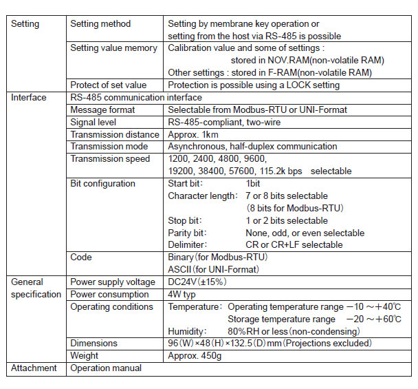
| Setting method | Settings are made by operating the membrane keys. Also, settings can be made from a host computer through the RS-485 interface. |
|---|---|
| Memory of set value | Calibration value and a part of set value: NOV.RAM (nonvolatile RAM) Other set values: F-RAM (nonvolatile RAM) |
| Protect of set value | Protect can be set by Lock switch and Lock parameter. |
| Setting items | Upper limit/ Lower limit/ Near zero/ Set point 1/ Set point 2/ Compensation/ Over/ Under/ Final/ Comparison inhibit time/ Judging time/ Complete output time/ Compensation feeding time/ Auto free fall compensation regulation/ Weighing function 1/ Weighing function 2/ Tare setting/ Tare display/ Digital low pass filter/ Moving average filter/ MD/ZT period/ ZT range/ Total comparison selection/ Total limit (most significant 4 digits)/ Total limit (least significant 5 digits)/ Count limit/ Weighing function 3/ Key invalid・Lock/ Input selection 1/ Input selection 2/ Output selection 1/ Output selection 2/ Error output selection/ Reserve output selection/ Password/ Bag clamp output time/ Discharging time/ Weighing start time/ AZ times/ Judging times/ Sequence mode 1/ Sequence mode 2/ Filling enhancement value/ Expanded function selection 1/ Expanded function selection 2/ Balance weight value/ Capacity/ Min. scale division/ DZ regulation value/ Display selection 1/ Gravitational acceleration/ Net over/ Gross over/ Display selection 2/ RS-485 I/F setting/ RS-485 Communication type/ RS-485 ID/ Transmission delay time/ Zero calibration/ Span calibration/ Equivalent calibration/ Option display |
| External signal (You can specify whether PNP (Source) type or NPN (Sink) type when order the F701-S.) | |
| Output signals (16) | SP1/ SP2/ SP3/ Complete/ Discharge/ Bag clamp/ Error selection 1,2/ Output selection 1 to 6/ Reserve 1,2 At signal ON, output transistor ON. * External voltage must be prepared separately by customer. |
|---|---|
| Input signals (16) | Operation permission/ Weighing start/ Stop/ Discharge command/ Manual discharge/ Discharge gate open/ Accumulation clear/ Input selection 1 to 6/ Code 1,2,4 Contact (relay, switch etc.) or non-contact (transistor, open collector etc.) can be connected. * External voltage must be prepared separately by customer. |
| Interface | ・ 485: RS-485 communication interface (Select from Modbus-RTU and original format) ・ 232: RS-232C communication interface (option) ・ BCO: BCD parallel data output interface (sink type) (option) ・ BSC: BCD parallel data output interface (source type) (option) ・ DAC: D/A converter (option) ・ ODN: DeviceNet interface (option) ・ PRF: PROFIBUS interface (option) * PROFIBUS-DPV0 ・ CCL: CC-Link interface (option) |
| Display section | |
| Display | 18.5mm in character height, Numerical display on LCD(7 digit) Sub display:7.3mm in character height (14 digit) |
|---|---|
| Indicated value | 5 digit sign: negative display at the highest digit |
| Accumulation value | 9 digit * This can be changed to “Accumulation count (4 digit)”, “Final(5 digit)”, “Code(1 digit)”, “Total discharge count (6 digit)” and “Discharge count (5 digit)”. |
| Display frequency | Select from 1, 2, 5, 10, 20 times/sec.(The system speed is 300 times/sec.) |
| Capacity | 5 digit |
| Min. scale division | Setting allowable in the range of 1 to 50. * Only the following settings are valid when OIML R76-1-compliant: 0.001, 0.002, 0.005, 0.010, 0.020, 0.050, 0.01, 0.02, 0.05, 0.1, 0.2, 0.5, 1, 2, 5, 10, 20, 50 |
| Decimal point | Select from 0, 0.0, 0.00, 0.000 |
| Over display | LOAD: A/D converter input over, OFL1: Net over, OFL2: Capacity +9 scale division, -OFL2: Capacity -over or -20 scale division over, OFL3: Gross over |
| Center zero | A true zero point or the center of each value is displayed. * Only true zero point is displayed when OIML R76-1-compliant. |
| Status display | CLAMP/ SP3/ SP2/ SP1/ HOLD/ COMPL./ ZT/ ZALM/ STAB/ TARE/ NET/ GROSS/ NZ/ D.CHG/ HI LIM/ HI/ GO/ LO/ LO LIM/ CZ/ LOCK |
| General performance | |
| Power supply voltage | AC100 to 240V (+10% -15%)(free power source 50/60Hz) |
|---|---|
| Power consumption | 15W max. |
| Inrush current | 2A, 3mSec: AC240V average load condition (cold start at room temperature) |
| Operating conditions | Temperature…Operation -10℃ to +40℃, Storage -20℃ to +85℃ Humidity…85% or less (non-condensing) |
| Dimensions | 192(W)×96(H)×140(D) mm (Projections excluded) |
| Panel cutout dimensions | 186 +2 -0(W)×92 +1 -0(H)mm * Installation panel thickness: 1.6 to 3.2mm |
| Weight | Approx. 2kg |
| Attachments | |
| AC input cord (Nominal rating 125V) 2m | 1 |
|---|---|
| Loadcell connector | 1 |
| Load cell connector rubber | 1 |
| External I/O signal connector | 1 |
| Operation manual | 1 |
| Rubber packing | 1 |
| BCD output connector(with BCD output option) | 1 |
| DeviceNet connector (with DeviceNet option) | 1 |
| CC-Link connector(with CC-Link option) | 1 |
Option
| Model | |
| 232 | RS-232C communication interface |
|---|---|
| BCO | BCD parallel data output interface (sink type) |
| BSC | BCD parallel data output interface (source type) |
| DAC | D/A converter |
| ODN | DeviceNet interface |
| PRF | PROFIBUS interface |
| CCL | CC-Link interface |
Optional accessories
| Model | |
| CAAC3P-P2 | AC input cord 2m |
|---|---|
| CAAC3P-CEE7/7-P1.5 | AC input cord (voltage resistance: 250V) 1.5m |
| CA4131 | (6-wired) cable with JRC connector at one end 3m |
| CA4230 | JRC-PRC (6-wired) conversion relay cable 0.3m |
| CA4311 | JRC-PRC (6-wired) conversion relay cable (4-wired to 6-wired) (for 520A use) 1m |
| CN3P-2P | 3P-2P converter plug for AC input cord |
| CN10 | Loadcell connector |
| CN34 | D-Sub 9p connector for RS-232C |
| CN51 | BCD output connector |
| CN52 | FCN series I/O connector (with cover) |
| CN57 | FCN series I/O connector (with diagonal cover) |
| CN71 | CC-Link connector |
| CND01 | DeviceNet connector |
Download
|
Product catalogue(PDF)
|
F701-S Product catalogue Download | |
|---|---|---|
|
Operation manual(PDF)
|
|
|
|
External dimention
|
DXF
(ZIP) |
|
|
PDF
|
||
|
Support tools
|
|
|
|
Software
|
||
- User registration is required to download operation manuals, external dimentions, support tools and software.
- Acrobat Reader software from Adobe Systems is required to view PDF files.
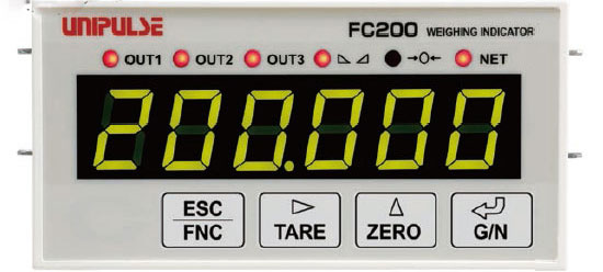
FC200
For simpler , Economical & more accurate weighing systems!
Product outline
For simpler and more accurate weighing systems!
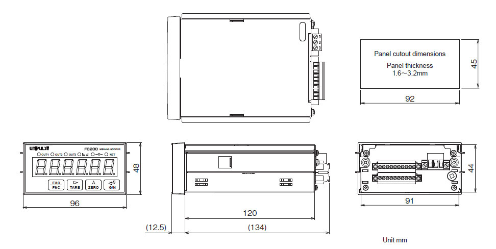
Compact size: DIN 96 x 48mm
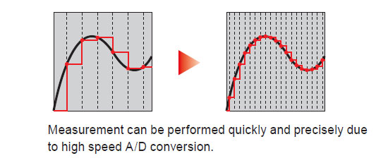
High-speed A/D conversion at 300 times/sec.
for weighing systems like bagging machines and hopper scales.
RS-485 as standard serial interface with multi-drop capability:
up to 32 control units on the same network!
High sampling rate & resolution
High-Speed A/D conversion and powerful digital processing capability of 300 times/sec. High resolution of 1/10000 in all input range. (internal 24bit)
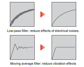
High performance filter
As it is resistant to vibration, measurement can be performed quickly and precisely.
Small and lightweight
96W×48H×132.5Dmm
Approx.450g
Improved visibility!
6-digits green LED display in 14 mm height & six status lights.
Equivalent input calibration
Theoretical calibration can be per formed easily by registering the capacity and rated output of load cells.
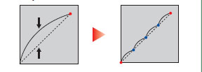
Multipoint calibration (linearization)
Three additional points can be defined in the middle between zero and span for better linearity.
Zero tracking function
Slow zero drift or shift of zero point due to temperature change etc. is utomatically corrected.
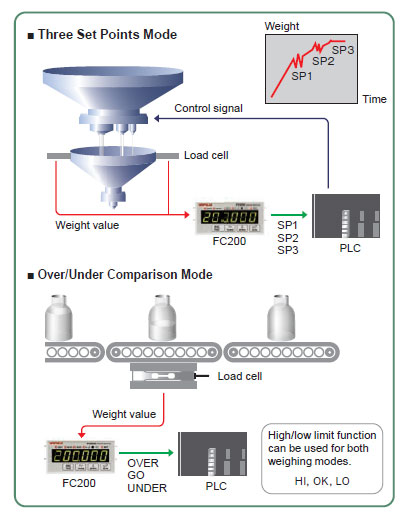
Application example
High/low limit function and two weighing modes:
(Three Set Points Mode & Over/Under Comparison Mode)
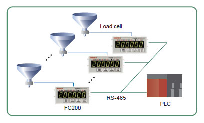
RS-485 as standard interface.
RS-485 (Modbus-RTU) multi-drop connection:
maximum of 32 control units on the same network!
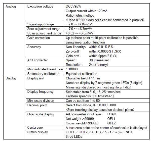
Specifications
External Dimensions
Download
|
Product catalogue(PDF)
|
FC200 Product catalogue Download | |
|---|---|---|
|
Operation manual(PDF)
|
|
|
|
External dimention
|
DXF
(ZIP) |
|
|
PDF
|
||
|
Support tools
|
||
|
Software
|
||
- User registration is required to download operation manuals, external dimentions, support tools and software.
- Acrobat Reader software from Adobe Systems is required to view PDF files.
F800
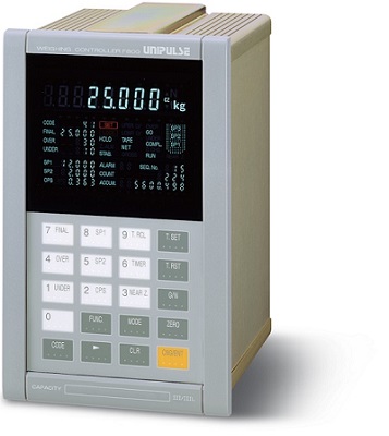
All-in-one type weighing indicator
Product outline
A weighing Indicator for auto weighing systems. F800 is compatible with a network with various PLCs such as DeviceNet and CC-Link. F800 is packed with the latest features supporting all weighing systems such as the code setting function that allows presetting of weighing conditions of up to 100 codes and the weighing sequence function that allows direct control of feeding and discharging gates only by giving the target weight value.
Specifications
Analog section|Setting section|I/O section|Display section|General performance|Attachments
| Analog section | |
| Excitation voltage | 10V DC ±5%, Output current; within 120mA (Up to 4 units at 350Ω are parallel-connectable) |
|---|---|
| Zero adjustment range | 0 to approx. 2mV/V (digital adjustment) |
| Gain adjustment range | 0.3 to 2.0mV/V (digital adjustment) |
| Min. input sensitivity | 0.3μV/count |
| Accuracy |
Non-linearity: within 0.01%/FS (Typ: 0.005%/FS at room temperature) Zero drift: within 0.1μV/°C RTI (Typ: 0.08μV/°C) Gain drift: within 15 ppm/°C (Typ: 5 ppm/°C) Noise: within 0.1μVp-p RTI (0.1 to 10 Hz) |
| Analog filter | Bessel low-pass filter (-12dB/oct.), Selectable from 2, 4, 6, 8 Hz |
| A/D converter |
Speed: 100 times/sec. Resolution: 16 bit (binary) |
| Min. display resolution | 1/10000 |
| Secondary calibration | Calibration can be carried out without an actual load by connecting a resistor to one of the bridges of a loadcell. |
| Setting section | |
| Setting method |
・ Keyboard operation (keyboard with a key click buzzer) ・ External setting is available by installing RS-232C option |
|---|---|
| Setting value storage |
・ Initial set values: NOV RAM (Non-volatile RAM) ・ Other set values: C-MOS RAM with backup of a lithium battery (Effective for more than 5 years depending on usage conditions and storage environment) |
| Setting value protection | Setting operation can be locked to prevent unauthorized modifications of default values and calibration by malfunction (LOCK) |
| Setting item |
・ Calibration: Zero calibration/ Span calibration/Balance weight value/ Capacity/ Min. scale division/ Over Net/ Over Gross/ Display frequency/ Decimal point/ 1/4 Scale display ON/OFF/ Unit/ Gravitational acceleration compensation ・ Comparative setting1: SP1/ SP2/ CPS/ Final/ Under/ Over/ AFF reg/ Compensation input timer ・ Comparative setting2: Near zero/ Lo/ Hi/ Preset tare weight/ Comparison inhibit time/ Judging time/ Compare time/ Discharging time/ AZ time/ Judging times/ Sequence mode ・ Function setting: Digital filter/ Motion Detection/ Weighing function1/ Weighing function2/ Weighing function3/ Function key inhibited/ RS-232C/ ID number setting/ Analog filter/ Zero tracking/ Measurement law/ Extended selection1 |
| I/O section | |
| External output signal (16) |
・ Logic…negative logic ・ Transistor open collector output. (Emitter=COM terminal) The output turns ON when the transistor turns ON. ・ Near zero/ SP1/ SP2/ SP3/ under/ go/ over/ complete/ discharge/ Lo/ Hi/ stable/ weight error/ error/ final error/ RUN |
|---|---|
| External input signal (23) |
・ Logic…negative logic ・ ON when shorted with COM terminals by contact (relay, switch, etc.) or non-contact (transistor, TTL open-collector output, etc.) ・ Gross or net/ digital zero/ tare on/ tare reset/ hold or judge/ feed or discharge/ accumulation command/ accumulation clear/ code setting/ start / stop/ discharge command/ compulsory discharge command/ discharge gate open/ discharge gate close/ code assign selection/ code assign input |
| Interface |
・ SIF: 2-wire type serial interface (standard); Interface to link with Unipulse printer or external display. ・ 232: RS-232C communication interface (Optional); Write (change)/read weight data, various statuses and setting values via commands from host computer. ・ BCO: BCD parallel data output interface (Option); Transmits weight data to a PLC or other BCD devices. ・ BCI: BCD parallel data input interface (Option); Parallel interface to receive setting values from external device.s ・ 485: RS-485 communication interface (Option); Compared with the RS-232C, longer-distance communications can be carried out. ・ DAC: D/A converter (Option); Weighing values are output as converted into analog signals of voltage and current. The zero output weight value and full scale value can be set. ・ ODN: DeviceNet interface (Option); Seamlessly connectable with DeviceNet-compliant Omron CompoBus/D. ・ CCL: CC-Link interface (Option); Serial bus interface for connection with PLC. |
| Display section | |
| Weight display | Numerical display (8-digit) by fluorescent display tube 12mm in character height |
|---|---|
| Weight value display | 5 digits Sign: Only a negative sign is displayed at the highest-order digit of the display. |
| Unit | t, g, kg, N, none selectablet |
| Decimal point | Display position selectable (zero blanking display by decimal point) |
| Display update rate | 3, 6, 13, 25 times/sec. selectable (However, the A/D conversion rate is fixed.) |
| Capacity | 5 digits settable |
| Over scale display | A/D converter input over(LOAD), Net over (5 digits settable)(OFL1), Gross weight beyond capacity + 9 scale divisions(OFL2), Gross over (5 digits settable)(OFL3) |
| Center zero display | Displays true zero point (1/4 scale division). |
| Status display | Fixed character display by fluorescent display tube (display item lighting) SET/ LOCK/ HOLD/ Z.ALM/ STAB./ T.SET/ NET/ GROSS/ RUN/ UPER LV/ LOWR LV/ NEAR Z./ SP1/ SP2/ SP3/ OVER/ GO/ UNDER/ COMPL/ D.CHG/ AFC |
| Setting value display | By fluorescent display tube 4mm in character height CODE/ FINAL/ UNDER/ OVER/ SP1/ SP2/ CPS |
| Accumulation display | By fluorescent display tube 4mm in character height COUNT (4-digit)/ ACCUM. (9-digit) |
| No. display | By fluorescent display tube 4mm in character height ALARM (2-digit)/ SEQ.NO. (3-digit) |
| General performance | |
| Power supply voltage | 85 to 110V, 102 to 132V, 170 to 220V, 187 to 242V AC (Please specify when ordering), 50/60Hz |
|---|---|
| Power consumption | Approx. 20VA |
| Operating conditions | Temperature: Working temperature range -10°C to +40°C; Storage temperature range -40 to +80°C Humidity: 85% RH or less (non-condensing) |
| Dimensions | 130(W)×207(H)×150(D) mm (protruding parts not included) |
| Panel cutout dimensions | 127(W)×200(H)mm (* Installation panel thickness: 1.6 mm or more) |
| Weight | Approx. 3 kg |
| Attachments | |
| Power supply cable (2m) | 1 |
|---|---|
| Spare fuse (1A) | 1 |
| Load cell input connector (Hirose JR16PN-7S) | 1 |
| Control signal input/output connector (DDK 57-30500) | 1 |
| Flathead screwdriver | 1 |
| Operation manual | 1 |
| BCD output connector (when BCD output option is selected) | 1 |
| BCD input connector (when BCD input option is selected) | 1 |
| DeviceNet connector (when DeviceNet output option is selected) | 1 |
| CC-Link interface (when CC-Link option is selected) | 1 |
Option
| Model | Interface (Optional slot・・・3: Please refer to the following table for the combination that can be installed.) |
|---|---|
| 232 | RS-232C communication interface |
| BCO | BCD parallel data output interface |
| BCI | BCD parallel data input interface |
| 485 | RS-485 communication interface |
| DAC | D/A converter |
| ODN | DeviceNet interface |
| CCL | CC-Link interface |
(Ref.) Assortment of options
| Number of install OP | BCD OUT (BCO) |
BCD IN (BCI) |
D/A (DAC) |
RS-232C (232) |
RS-485 (485) |
DeviceNet (ODN) |
CC-Link (CCL) |
||
|---|---|---|---|---|---|---|---|---|---|
| 1 | ◎ | ||||||||
| ◎ | |||||||||
| ◎ | |||||||||
| ◎ | |||||||||
| ◎ | |||||||||
| ◎ | |||||||||
| ◎ | |||||||||
| 2 | ◎ | ◎ | |||||||
| ◎ | ◎ | ||||||||
| ◎ | ◎ | ||||||||
| ◎ | ◎ | ||||||||
| ◎ | ◎ | ||||||||
| ◎ | ◎ | ||||||||
| ◎ | ◎ | ||||||||
| ◎ | ◎ | ||||||||
| ◎ | ◎ | ||||||||
| ◎ | ◎ | ||||||||
| ◎ | ◎ | ||||||||
| ◎ | ◎ | ||||||||
| ◎ | ◎ | ||||||||
| ◎ | ◎ | ||||||||
| ◎ | ◎ | ||||||||
| 3 | ◎ | ◎ | ◎ | ||||||
| ◎ | ◎ | ◎ | |||||||
| ◎ | ◎ | ◎ | |||||||
| ◎ | ◎ | ◎ | |||||||
| ◎ | ◎ | ◎ | |||||||
| ◎ | ◎ | ◎ | |||||||
| Number of install OP | BCD OUT (BCO) |
BCD IN (BCI) |
D/A (DAC) |
RS-232C (232) |
RS-485 (485) |
DeviceNet (ODN) |
CC-Link (CCL) |
||
Optional accessories
|
Model
|
Description
|
|---|---|
| CAAC2P-P2 | AC input cord 2m |
| CAAC3P-CEE7/7-P1.5 | AC input cord (withstand pressure: 250V) 1.5m |
| CN3P-2P | 3P-2P conversion plug for AC input cord |
| CA4131 | (6-core) cable with JR connector at one end (cable end is separated) 3m |
| CA4230 | JR-PRC conversion relay (6-core) cable 0.3m |
| CA4311 | JR-PRC conversion relay (6-core) 4-wire type / 6-wire type (for 520A) 1m |
| CN21 | BCD input/output connector |
| CN22 | 57 series 50p connector for external I/O |
| CN35 | D-Sub 25p connector for RS-232 |
| CN71 | CC-Link connector |
| CND01 | DeviceNet connector |
Download
|
Product catalogue(PDF)
|
F800 Product catalogue Download | |
|---|---|---|
|
Operation manual(PDF)
|
||
|
External dimention
|
DXF
(ZIP) |
|
|
PDF
|
||
|
Support tools
|
||
|
Software
|
||
- User registration is required to download operation manuals, external dimentions, support tools and software .
- Acrobat Reader software from Adobe Systems is required to view PDF files.
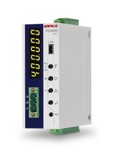
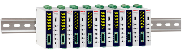
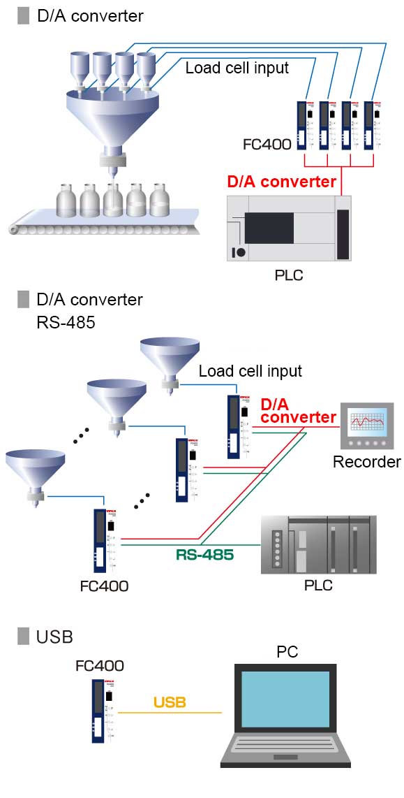
FC400
DIN-rail mount weighing indicator with D/A converter
Product outline
FC400-DAC is a compact weighing Indicator with D/A converter. It is suitable for many weighing applications such as hopper scale, packing scale, weight level meter, etc….
Either voltage or current output, corresponding to the indicated value, is available.
It can be fit into a limited space!
Light weight & compact body for 35mm DIN rail mount.
External dimension: 34(W)×88(H)×91(D)mm (not including projection) Weight: Approx. 210g
Various interface
Equipped as standard with D/A converter, RS-485 , and USB interface.
High-speed sampling & high resolution
High-speed A/D conversion rate at 1200 times/sec. & high display resolution capability of 1/100000.
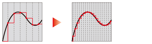
The high-speed A/D converter enables the faster and more accurate weighing.
Various features
■ High-performance filter
With the powerful filter against noise, high-speed an high-accuracy weighing can be achieved.
■ Auto filter adjustment
The filter is automatically adjusted to reduce the noise when the auto adjustment key is pressed.
■ Equivalent input calibration
Theoretical calibration can be performed easily by registering the capacity and rated output of the load cell(s).
■ Multipoint calibration (linearization)
Three additional points can be defined in the middle between zero and span to improve the linearity.
■ Input conversion value display
The output signal level of the connected load cell can be displayed in mV/V/ for monitor purpose.
■ Basic weighing process control function
Sequential control can be performed without external devices like PLC.
Specifications
Analog section|Display section|External signal|Interface|General performance|Attachments
| Analog section | |
| Excitation voltage | DC5V±5% Output current: 90mA Ratiometric method (up to six 350Ω load cells can be connected in parallel) |
|---|---|
| Signal input range | -2.5 to 5.1mV/V |
| Zero adjustment range | Automatic adjustment by digital processing: -0.5 to 2.0mV/V |
| Gain adjustment range |
Automatic adjustment by digital processing: 0.02 to 3.0mV/V |
| Gain correction | Multipoint calibration function: Up to three additional points between zero and span points can be defined. |
| Minimum input sensitivity | 0.15μV/count |
| Accuracy | Non-linearity: within 0.01%FS Zero drift: 0.0002%FS/℃ Typ Gain drift: 1ppm/℃ Typ |
| Filter | Digital low-pass filter: 0.1 to 300 Hz Moving average filter: OFF, 2 to 512 times |
| A/D converter | Rate: 1200 times/sec. Resolution: 24 bit(binary) |
| Display section | |
| Display unit | 8mm character height, 7-segment green LED numeric display |
|---|---|
| Indicated value | Max. 6 digits |
| Refresh rate | Selectable from 3, 6, 13, or 25 times/sec. |
| External signal | |
| External output (5) |
Selectable outputs. Transistor open collector output. Vceo=30V,Ic=50mA |
|---|---|
| External input (3) |
Selectable inputs. Either contact type (relay, switch etc.) or non-contact type (transistor, photocoupler etc.. ) can be connected. ON when short-circuited with COM. * The external power supply (DC24V) needs to be prepared by user. |
| Interface | |
| USB | USB interface |
|---|---|
| 485 | RS-485 communication interface (select either Modbus-RTU or UNI format) |
| DAC | D/A converter (select either voltage or current output) |
| General performance | |
| Operating voltage | DC24V (±15%) |
|---|---|
| Power consumption | 3W typ |
| Operation condition | Operating temperature range: -10℃ to +50℃. Storage temperature range: -20℃ to +85℃ Humidity: 85%RH or less (non-condensing) |
| Dimensions | 34(W)×88(H)×91(D)mm (not including protrusions) |
| Weight | Approx. 210g |
| Attachments | |
| Jumper wire | 2 |
|---|---|
| Mini driver | 1 |
| Various I/O connector | 3 |
| Quick manual | 2 |
Download
|
Product catalogue(PDF)
|
FC400 Product catalogue Dowmload | |
|---|---|---|
|
Operation manual(PDF)
|
|
|
|
External dimention
|
DXF
(ZIP) |
|
|
PDF
|
||
|
Support tools
|
||
|
Software
|
||
- User registration is required to download operation manuals, external dimentions, support tools and software.
- Acrobat Reader software from Adobe Systems is required to view PDF files.
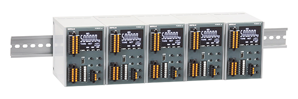
FC500
DIN-rail mount weighing indicator with RS-485 interface
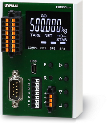
Product outline
FC500 is a weighing indicator equipped as standard with RS-485 interface. It is ideal for a variety of weighing applications like hopper scales, bagging machines, and level meters. Measured data and results can be collected using RS-485 interface.
Lightweight and compact body to fit into limited space in a control panel
Light weight & compact body for 35 mm DIN rail mount Dimensions: 65(W)×94(H)×108(D) mm (Not including projections) Weight: Approx. 370 g
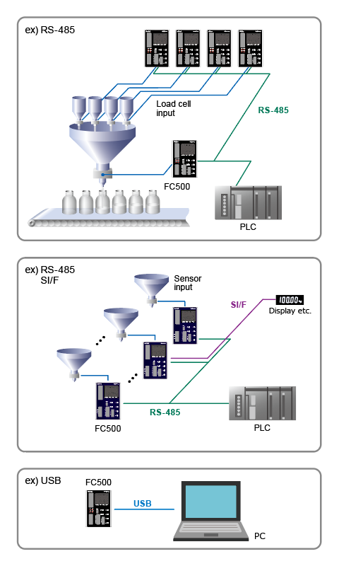
Various interfaces
RS-485、SI/F、USB interfaces is equipped as a standard feature
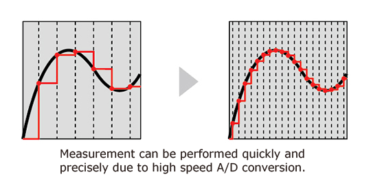
High sampling rate & resolution
High-Speed A/D conversion and powerful digital processing capability of 1200 times/sec.(Convertible to 300 times/sec.). High display resolution of 1/100000 (max).
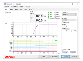
Application software for USB interface(Free software)
With communication through USB interface, logging, graph, display, setting parameters, and calibration can be done.
Various functions useful for automated weighing systems
■ Equipped with data memory function Latest 100 data of calibration value and error information with clock time are recorded and can be checked via USB interface.
■ Basic weighing process control function Equipped with weighing sequence function to control feeding/discharge gate.
■ Memory for 32 weight settings 32 different weight settings can be saved in the memory and selected through I/O or interface. Batch weighing can be performed easily.
■ Equivalent input calibration Theoretical calibration can be performed easily by registering the capacity and rated output of load cells.
■ Input conversion value display The output signal level of the connected load cell can be displayed in mV/V for monitor purpose. Malfunction indicator or faulty sensor can be differentiated easily.
■ Multipoint calibration (linearization) Three additional points can be defined in the middle between zero and span for better linearity. Even though the scale has poor linearity, it can be corrected to be a highly accurate scale
Specifications
Analog section|Display section|External signal|Interface|General specifications|Attachments|Optional accessories
| Analog section | |
| Excitation voltage | DC 5 V±5% Output current: within 90 mA Ratiometric method (Up to 6 350 Ω load cells can be connected in parallel) |
|---|---|
| Signal input range | -2.5 to +5.1 mV/V |
| Zero adjustment range | Automatic adjustment by digital processing -0.5 to +2.0 mV/V |
| Span adjustment range | Automatic adjustment by digital processing 0.005 to 3.2 mV/V |
| Linearization function | Up to three point multi-point calibration is possible using linearization function |
| Min. input sensitivity | 0.15 μV/count |
| Accuracy | Non-linearity: within 0.01% FS Zero drift: 0.0002% FS/℃ Typ. *When calibrated by 3 mV/V Gain drift: 1 ppm/℃ Typ. |
| Filter | Digital low-pass filter: 0.1 to 300 Hz Moving average filter: OFF, 2 to 512 times |
| A/D converter | Speed: 1200 times/sec.(Convertible to 300 times/sec.) Resolution: 24 bit (binary) |
| Display section | |
| Display unit | Character height 11 mm |
|---|---|
| Display value | Up to 6 digits. Sign:Minus display on the highest digit |
| Unit | t/ g/ kg/ lb/ N/ None |
| Display frequency | Selectable from 1, 3, 6, 13, 25 times/sec. |
| Status display | COMPL./SP1/SP2/SP3/HI/GO/LO/NZ/TARE/NET/HOLD/ZALM/STAB |
| External signal | |
| Input signal (5) |
Selectable/configurable <No-voltage contact input> Input is ON when shorted to COM terminal by contact (relay, switch, etc.) or non contact (transistor, photocoupler, etc.). <Voltage input plus common/ minus common shared>(specifies at time of order) Input is ON when a voltage is applied in between to input terminal and COM terminal by contact (relay, switch, etc.) or non contact (transistor, photocoupler, etc.). Rated voltage:DC 27.6 V or less “ON”:when the voltage is above DC 9 V (Load Current:approx. 10 mA at DC 24 V), “OFF”:below DC 3 V. |
|---|---|
| Output signal (5) |
Selectable/configurable PhotoMOS relay output (common for sinc and source type) Vceo = 30 V、 Ic = 50 mA |
| Interface | |
| 485 | RS-485 interface (Selectable from Modbus-RTU or UNI-Format) |
|---|---|
| SIF | SI/F 2-wire type serial interface. |
| USB | USB interface |
| General specifications | |
| Power supply voltage | DC 24 V (±15%) |
|---|---|
| Power consumption | 4 W typ |
| Operating conditions | Operating temperature range: -10℃ to +50℃ Storage temperature range: -20℃ to +85℃ Humidity: 85% RH or less (non-condensing) |
| Dimensions | 65(W) × 94(H) × 108(D) mm (Not including projections) |
| Weight | Approx. 370 g |
| CE marking certification | EMC Directives EN61326-1 |
| Attachments | |
| Operation manual | 2 |
|---|---|
| Jumper wire | 2 |
| Power connector | 1 |
| Mini driver | 1 |
| I/O connector | 1 |
| RS-485 connector | 1 |
Option accessories
| CN7B | Power connector (Same as the attachment) |
|---|---|
| CN7D | I/O connector (Same as the attachment) |
| CN7C | RS-485 connector (Same as the attachment) |
Please note that there are possibilities of individual differences in a color tone on display devices such as LEDs, fluorescent display tubes and LCDs due to manufacturing process or production lots.
Download
|
Product catalogue(PDF)
|
FC500 Product catalogue Download | |
|---|---|---|
|
Operation manual(PDF)
|
||
|
External dimention
|
DXF
(ZIP) |
|
|
PDF
|
||
|
Support tools
|
||
|
Software
|
||